This project is to build a cabinet for a corner of the dining room. The size is constrained by the wall openings and the desire to put the silverware case on the top at a reasonable height. The style is constrained by a desire to roughly match the style of the existing dining room furniture–and by my level of ability.
Here’s the initial ‘design document’. The first version was a rough hand-drawn sketch over which I drew straight lines and added some details. Measurements are approximate and there is some flexibility in the final size.
This is going to be a face-frame cabinet made of solid oak with an oak plywood bottom shelf. It will have one oak plywood middle shelf that might be adjustable. TBD. The doors will be raised panel. This is new territory for me and is something I have wanted to learn. The top is also TBD: possibly interesting, thick oak; possible stone. That choice is up to the design consultant. (AKA, the customer. AKA, my wife.)
Preparing the Wood
Step 1 was to put together a list of the wood pieces needed. For the face frame, door stiles, and base the pieces are pretty obvious. The sides will have to be made up from multiple pieces of oak since I don’t have anything wide enough.
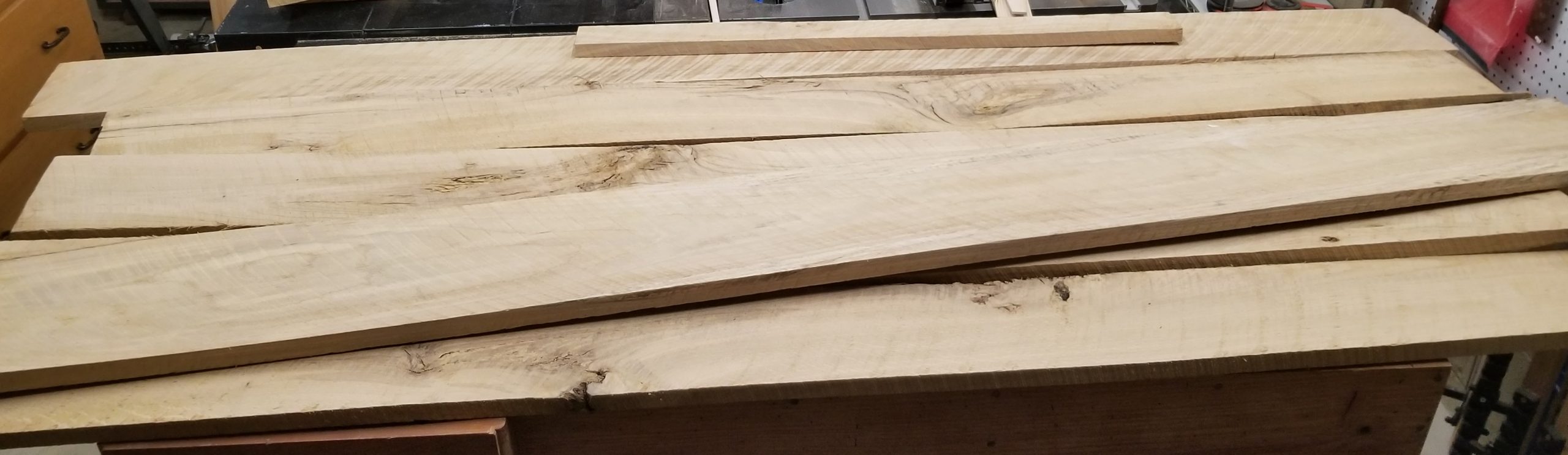
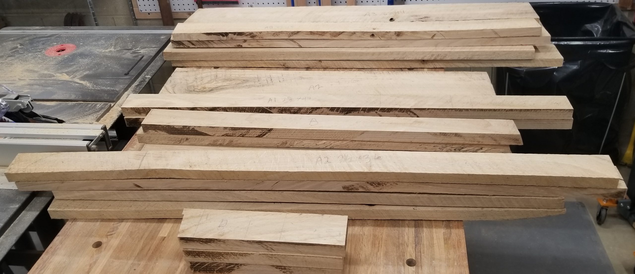
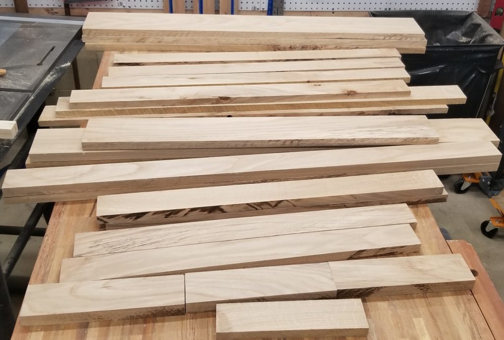
Step 2 was to mark out where these pieces could be taken from a bunch of rough-sawn oak boards. These boards came from my dentist’s father who has property out near Cleveland. When a tree comes down–or needs to be taken down–he saws it into planks and ages it in the barn. The are rough and bend in all directions. But they clean up nicely.
Next, cut them to rough size, as in a little bigger than finished size. There’s no way to flatten the boards at full size; there is just too much movement.
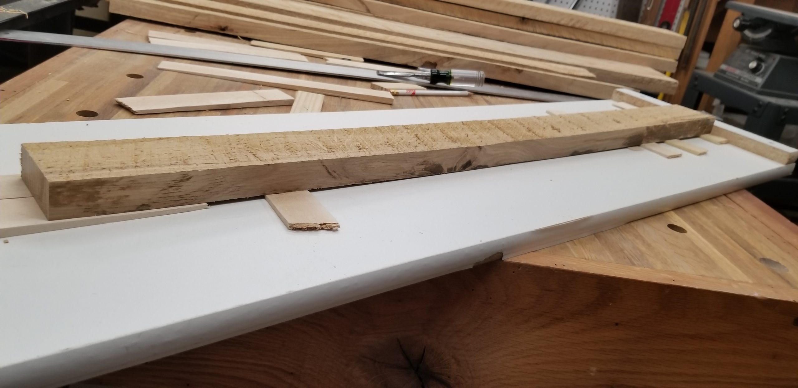
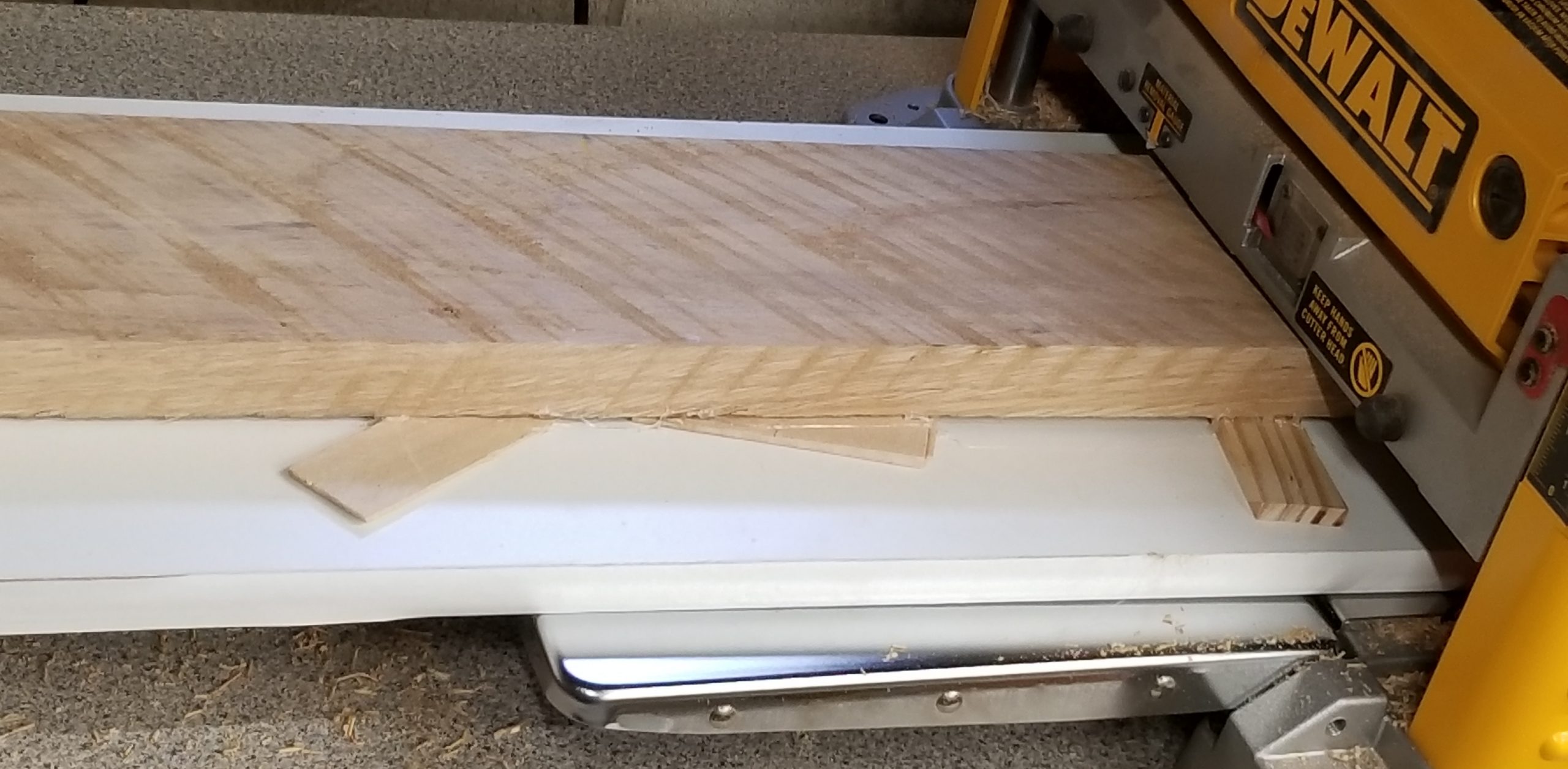
Now to flatten them on one side. Borrowing a technique I picked up on the internet, I built a sled for the planer. The boards are stabilized with shims and then glued down with hot glue. This works surprisingly well. I then take multiple passed through the planer until the top is flat and smooth. Rinse and repeat for all 25 pieces that were marked out.
Once one side has been flattened, the second side can be planed down without the need for the sled. I planed them just enough to get a flat, smooth surface. Final thickness planing will be done as needed for each piece.
Making the Side Panels
The sides will be about 14″ by about 42″. To get this, several boards will be planed to a common thickness, straightened, and jointed. The final thickness will be dictated by the boards that form each side. Since one board could not be made flat and smooth until it was about 11/16″, that was the final size.
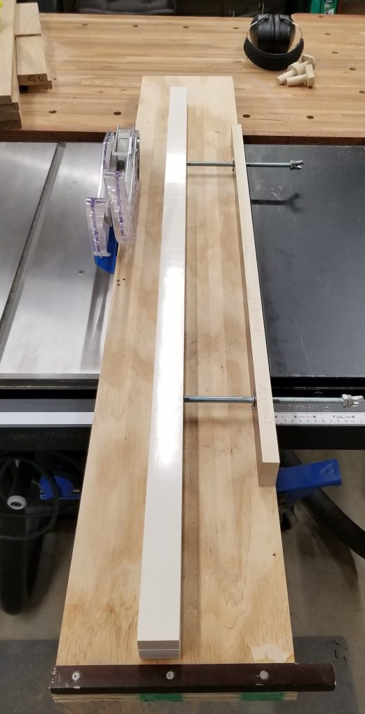
Straightening the boards takes a similar path to planing them. I build a sled for the table saw that rides the slot that the miter gauge uses. It has an adjustable, solid rail that is used to line up a board with the edge. The edge of the sled touches the saw blade, acting as a zero-insert on one side. The board to be trimmed is set with just enough overhang to get a complete straight edge on one side. Cutting the other side straight is done without the sled.
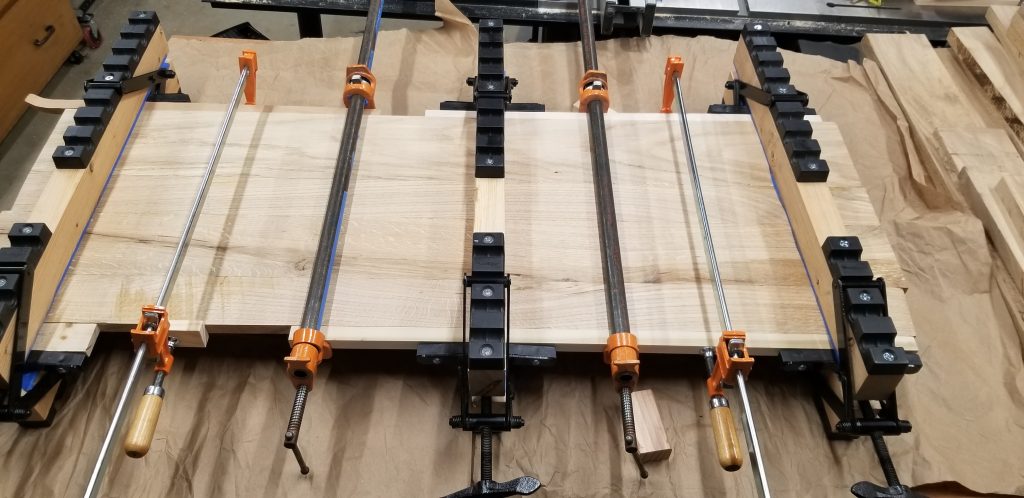
Having jointed the pieces, they are glued up and clamped. Here’s one side panel waiting for the glue to dry.
A Little More Planning
I approach many of me woodworking projects the same way I often approach software projects. I know what the end goal is and can see how to get started. But I don’t try to lay out all the details at the outset. Instead, I take an iterative approach where I refine the design as I go.
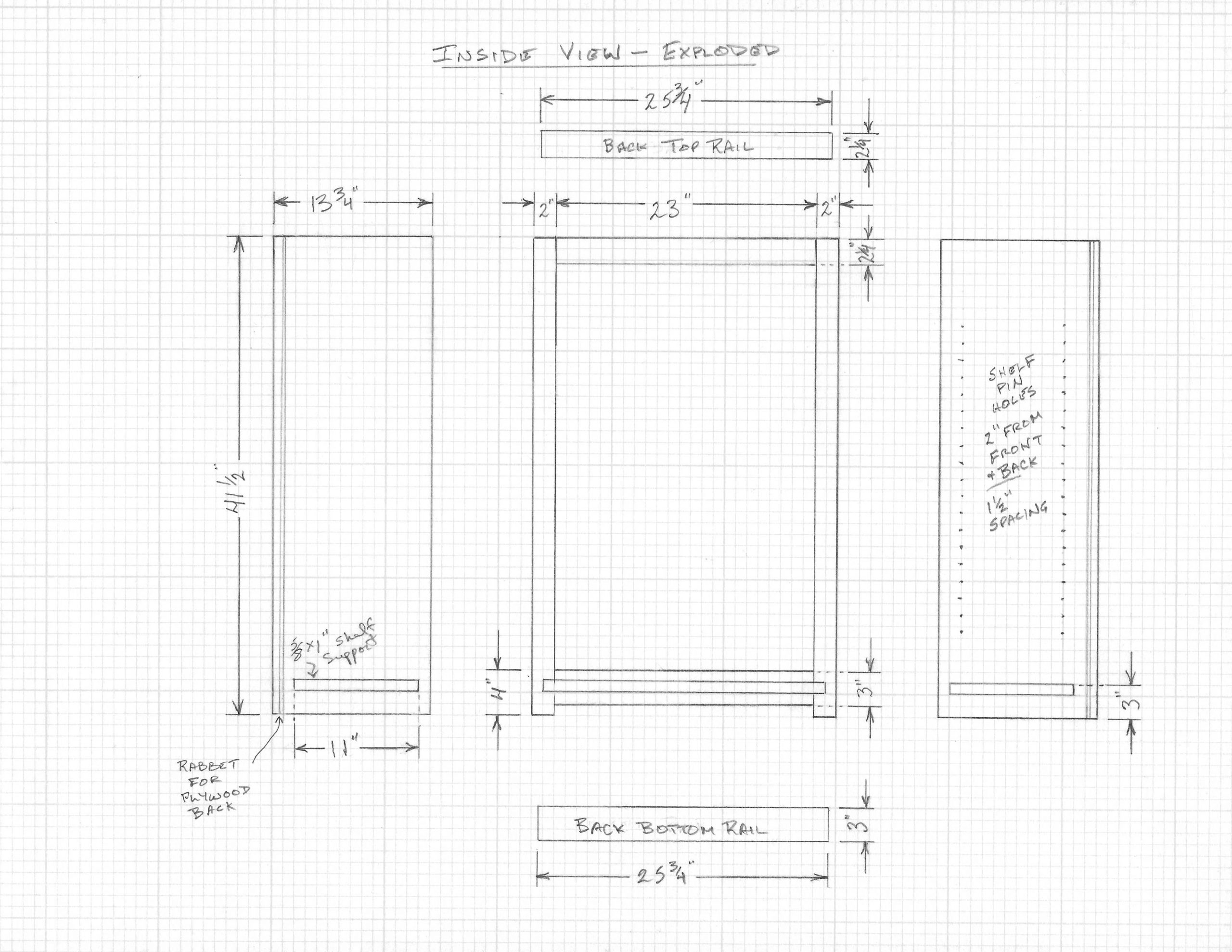
Here’s a drawing of the face frame and sides, seen from the inside and laid flat.
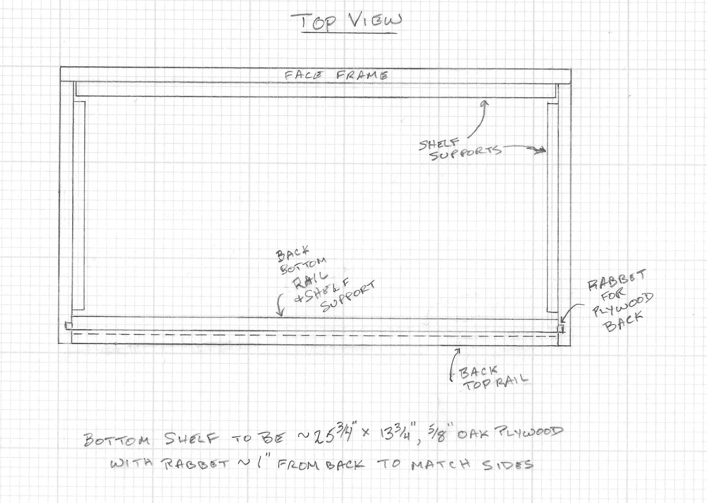
And here’s a top-down view.
At this point, I know where I’m going and can start to plane and cut the pieces needed for the face frame, the back rails, and the shelf supports. Final size adjustments will be made as needed.
We have a Leisure Travel Van (LTV) Unity RV. Love it. But there is always something you can do to personalize, customize, or upgrade an RV. In this case, it is the dining area table top
Note: This post is part description of what I did and part advice on how to do something similar if you are so inclined. All of the measurements can be adjusted to whatever suits your project.
The Unity came with a functional table top that was about 24″ square and had two leaves that folded out from the top to give about 39″ width. It fits well between the seats and can be used with the leaves out or not. But there were a few things that led me make changes.
The Table Leg
The table is mounted on a fixed post between the seats. Even with the leaves folded up, it was inconvenient to go from the van driving or passenger seat into the back ‘house’ area.
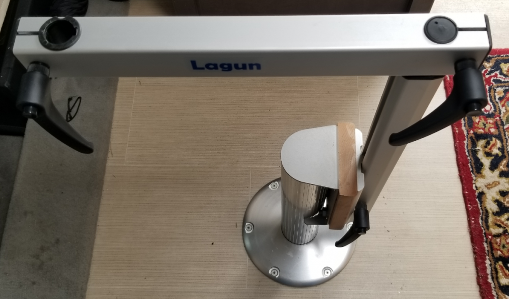
So the first change was to install a Lagun leg. This is an articulated post arm that lets you rotate the top and swing it over to the side.
That solved the access problem.
Side note: This is a Lagun brand leg. LTV now provides their own version customized to their purpose. With the Lagun leg, the position of the table top ends up slightly more forward than desired. My solution was to insert a 1″ block of wood between the post mount and the Lagun leg mount. Good enough.
The Table Top
That was fine for a while but a few things about the top bugged me.
Because the leaves folded out from the top and rested on simple hinges, they developed a droop. Not huge but enough that the surface wasn’t flat.
If you were using the table with the leaves folded up, and then decided to open the leaves, you had to remove everything from the table, open the leaves, and put everything back.
The top was made of particle board with a laminated surface. Unsurprisingly, over time it began to show chipping on the edges.
Also because of the laminated particle board, the edges were square. That gets annoying and even painful if you are resting your wrists on the edge.
So… Time to make a new top.
These are the basic design requirements for the new top.
Dimensions to be similar to original table top. Roughly 24×24″ closed and 24×39″ open. Finished thickness of 11/16″.
Weight to be no more than original table top.
Construction to use real wood. No laminates, plywood, particle board, etc.
Leaves that fold under so that they can be opened without disturbing what is already on the table.
Leaves must not droop when opened. (Not when new and not over time.)
All edges to be softened (rounded) for comfort.
Must mount on the existing Lagun leg.
Oh, and it should look appealing.
The Build
I am a fan of laying up multiple strips of wood to form a panel. Not only do I like the look of it, but
I don’t have to find, and work with, 24′ wide slabs of wood, and
the resulting panel resists warping and cracking.
Diagram
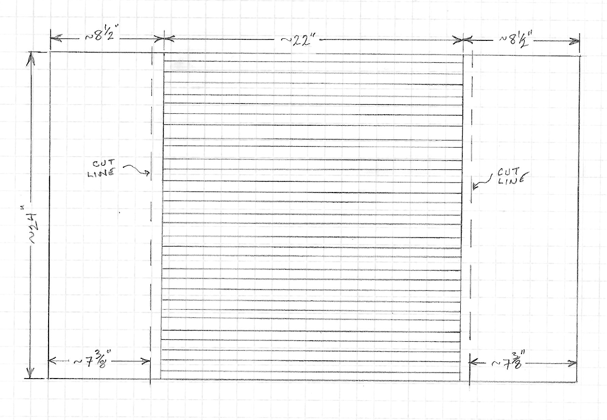
Here is a drawing of the general layout. The main top part of the table will be the area between the “cut lines”. The parts outside the cuts are the leaves.
Note that all dimensions are approximate. You want the table top to be about 24″ square when closed up and about 24″ x 39″ when opened. A half inch here or there isn’t going to make much difference.
Step 1: Select the Woods.
They should be all relatively hard woods to handle the wear and tear of a kitchen table. I’ve used a variety of woods that were lying around the shop: mahogany, oak, maple, and walnut. Plus one board purchased for the leaves which will be solid to maintain strength both in the leaf and at the joint.
Be sure to have your design consultant with you at this stage. I’m good with the engineering and construction but not so hot on colors and finish elements. The fact that the top looks so good is entirely down to my wife. She has an eye for this. I don’t.
Step 2: Prepare the Wood Strips
The strips of wood vary from about 3/4″ to 1-5/8″ width and are planed to roughly 1″ thickness. They must be planed or jointed to be co-planar to ensure a tight fit between them with no visible gaps. If they do not sit tightly together before being glued, there will eventually be cracks formed between them.
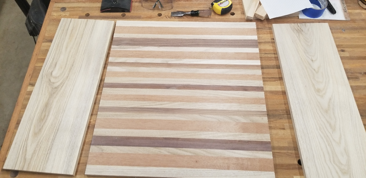
These strips form the main part of the table. They should be at least 24″ long to allow for trimming to final size of 21-3/4″. There must be enough of them to achieve the full table top width of 24″. I recommend making the outermost strips from the same board used to make the leaves. This adds a nice border effect to the top.
At least two of the strips should be closer to 30″ long. These will be protection against snipe when planing the panel.
Step 3: Initial Panel Glue-up
Unless you have a 24″ or wider plane, you will need to glue up two or more panels that will later be glued together. My plane can handle 12-1/2″ so I went with two panels.
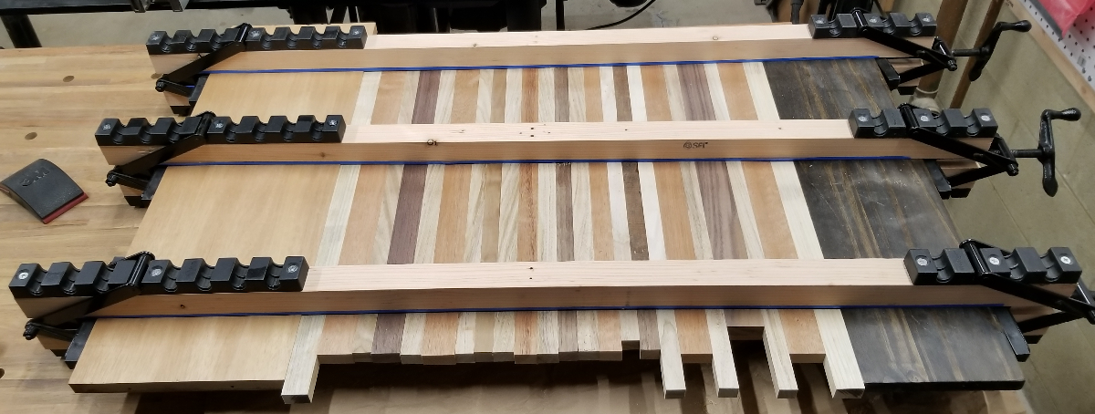
For each panel, I used my 24″ panel clamps. (See this post for more info on panel clamps.) I glued up the strips for one half of the table top, inserted extra boards on the outside edges to spread the pressure, and clamped them tight. Note that I placed one longer strip in each, as mentioned earlier, to fight snipe.
After giving it overnight to cure, I did the same again for the other half. I could have done both halves in my larger clamps but gluing and positioning that many strips is pushing the limit of initial drying time.
Step 4: Preparing the Leaves
I rough cut the wood for the leaves to slightly more than the final dimensions. So, about 30″ long by 9″ wide. I then planed it to about 1″ thick–similar to the initial thickness of the strips for the main part of the table. It is important to prepare the leaves at this stage because all the pieces must be planed together in the next step.
Step 5: Thickness Planing
After using a chisel to remove most of the glue squeeze out, it was off to the plane to set the thickness.
I planed the wood down in small increments: initially 1/32″, later 1/64″. I rotated through both glued-up panels and both leaves. At each pass I turned the boards over so that both sides benefited from planing. Once the thickness was down to 11/16″, it was done.
Step 6: Main Top Panel
We still have two ~12″ panels for the main top and it is time to glue them together.
For this step, I converted my 24″ clamps to 48″ clamps. (These clamps have a slight bow in them to ensure pressure in the center where these two panels will meet.)
Using two wide boards on the outside to spread pressure and protect the work pieces, the two halves are glued and aligned as closely as possible. A rubber hammer helped to tap the center to get the joint completely aligned. Then it’s another overnight wait for the glue to set.
After removing the clamps, the center strip is cleaned of glue squeeze out and sanded to remove any remaining misalignment or glue marks. Getting this joint right is why it is important to plane the pieces together and to be meticulous about the alignment in the glue-up.
Step 7: Trim the Top
Now that the top is built, cut it to size. The ends of the strips will be various uneven lengths and have to be cut square and clean to allow for attaching the leaves. Using the table saw, I cut the ends off on each side to get a final width of 21-3/4″.
Step 8: Attach the Leaves
At this point, the leaves do not have hinges and haven’t been shaped. They are also probably slightly bigger than final size. Trim the width of the leaves so that the total width of the leaves plus main top comes to 39″.
Now is the time to attach the boards. So, back to the long clamps. Glue up the leaves to the outside of the main top with the main top rotated 90 degrees so that the ends of the strips are glued to the leaves.
Take all the same care as previously and let it set up overnight. Once set, clean up the glued joints and sand as needed.
Step 9: Cutting the Leaves
Before cutting the leaves loose from the top, carefully trim the ends of the leaves to match the width of the top. The boards for the leaves were originally cut extra long to allow for snipe protection. The final size should be made in this step.
The finished size of the leaves should be about 7-3/8″. Measuring in from the outer edge and cutting, this will leave about a 1″ piece of the leaf board attached to the main top. This provides a nice border effect to the top. It also provides strength to the ends of the strips that will need to hold the hinges.
Step 10: Prepare for the Hinges
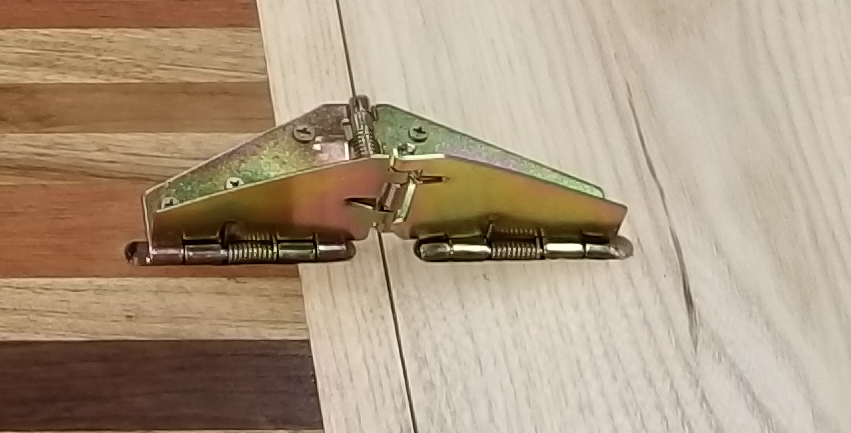
Oh yes, did I mention the hinges? To get leaves that fold up from the bottom and make a stable flat surface, you need special hinges. You want the hinges used by restaurants to convert a square table into a larger round table. I found these in two sizes. As usual on Amazon, there are multiple vendors selling the same hinges. The larger size has the advantage of a clip that holds the hinge closed when the leaf is under the table. But it is large and very heavy. The smaller one is perhaps half the weight and, sadly, doesn’t have that clip. But the smaller one–at about 6″ when opened as in the picture–is the right choice.
The hinge mechanism requires a groove to be cut in the wood so that the wings can lie flat. Align the main top and the leaves as they will be when finally assembled. Determine hinge location and mark it across the length of the hinge. Mark the length of the needed groove on both the top and the leaf.
(The folding part of the hinge must be on the joint between the leaf and the top. How far in from the side is a balance. Too far apart and they may allow the center of the leaf to dip. Too close together and you will have trouble reaching under the table to close the hinge.)
Use your favorite tool to create grooves that the hinge can sit in. I made a jig and used a 1/4″ round nose router bit to make the grooves. Do not try to router it freehand.
Do not install the hinges yet.
Step 11: Rounding the Corners and Edges
Choose an appropriate radius and round the corners of the main table top and the leaves using a band saw, jig saw, or whatever works for you.
Using a router and a small round-over bit, round off the top edges or the main table top and both leaves. (A 1/4″ bit worked for me but size it to the hinge you have.) Next, round off the bottom edges of these pieces BUT do not round off the bottom off the joints between the main table top and the leaves. Those edges can be eased a small amount with sanding.
Step 12: Test Assembly
At this point, you can confirm the hinge placement and ensure that everything will fit properly. If you install the hinges, don’t tighten the screws fully and don’t exercise the hinge. This is just making sure the fit is right.
Step 13: Sanding and Finish
Sand all surfaces until smooth. Sand the corners and round-overs as needed to clean up any issues from rounding the corners and to get a smooth feel.
The choice of finish is up to you. I used a water-based, satin finish polyurethane. I usually like to go with tung oil or other natural finishes. But this is going to have to stand up to spills, sunlight, etc.
Step 14: Final Assembly
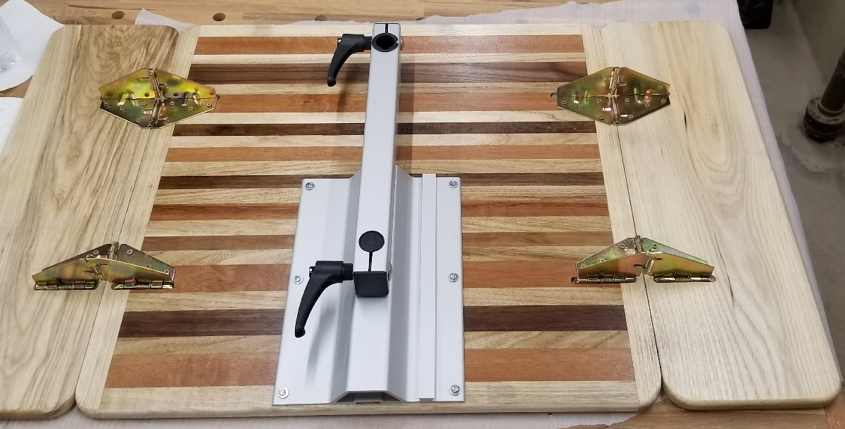
After you finish the finish, install the hinges fully and test that they work as expected. Install the Lagun leg mount–or whatever mounting system you are using. In my case, it goes in the center at one edge of the top. Your mileage may vary.
NOTE: Be sure to mount the hinges with the screws toward the middle and the raised part toward the outside edge. You will close the leaves by reaching under the top and pulling on the hinges.
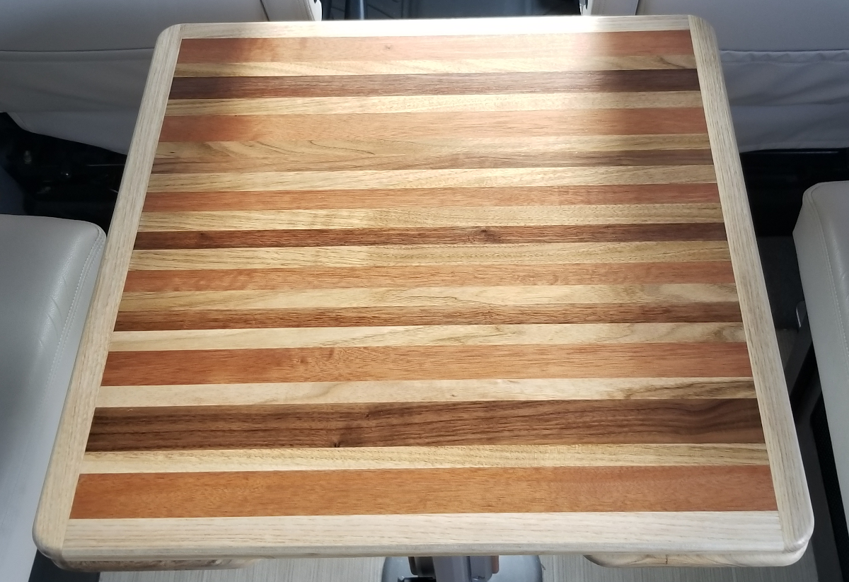
Step 15: Install It
Well, that does it. Not a quick project but the results are so worth it.
A Final Note
Because the hinges don’t have a clip to keep them closed when the leaves are down–as in the photo above–the leaves do wobble a bit on bumpy roads. This is a minor annoyance. If I come up with a good solution, I will update this post.
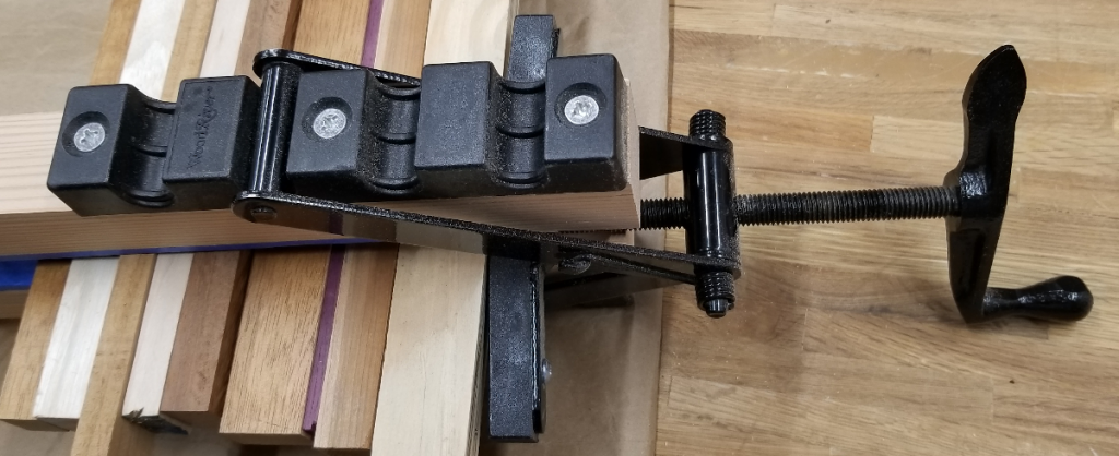
A few years ago, I bought a set of hardware for panel clamps. They have been indispensable in several of my projects. So I thought I would write up some notes on how they work and how I have used them.
The clamps I bought go under several brand/seller names, such as DCT and Peachtree. They go for about $25 to $30 per set. I bought three.
What really makes these great is that they supply pressure in four directions. Not just from both ends, but top and bottom also. This is essential in keeping the panel flat while the glue dries.
Initially, I used 24″ pieces of 2×2 as rails to form the clamps. This gave a working area of at least 18″ which was enough for the projects I was doing. (One was a cradle that needed side panels glued up. Others were cutting boards made for family and friends.) For those applications, straight 2×2 rails were sufficient to provide the top/bottom pressure.
More recently, I made a table top that required me to clamp about 39″ in the final glue-up. So I needed longer clamps. Mostly, this simply requires removing the hardware from the existing boards and attaching to longer ones. However, I was concerned about the clamps exerting sufficient top/bottom pressure at the center of that longer run.
Curving the Rails
To ensure pressure at the center point, I needed to cut a gentle curve in the rails. Not something I wanted to try on the band saw.
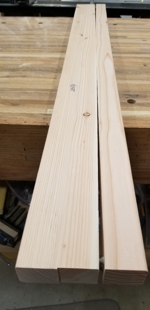
The solution was to force a curve in the rail in the opposite direction and then cut that side flat on the table saw.
I took a full 2×4, drilled holes in the middle to allow me to ‘capture’ the center of the rail with long screws, and inserted a #12 screw at each end protruding enough to give the desired curve.
Next, I attached a rail and used the center screws to pull it tight to the 2×4. I ran it through the table saw cutting off the curve to match the center.
Removed from this jig, the rail now has the desired curve.
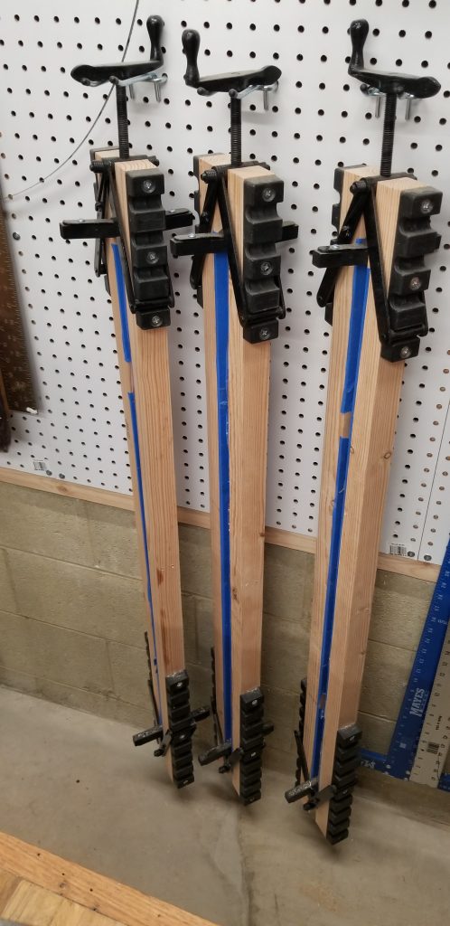
After attaching the hardware to each end of six rails, I have three clamps capable of handling over a 40″ glue-up.
The final step for both the 24″ and 48″ rails is to cover the working faces with painters tape. This prevents the clamp from becoming part of the work piece due to glue squeeze-out.
Using the Clamps
When using the clamps to make a panel there are a few things to keep in mind.
Use extra, unglued boards at each end to distribute the pressure and reduce the chance of damage to your work piece. These boards should be slightly thinner than the work pieces being clamped.
Have the boards that form the panel machined to roughly the same thickness. But be sure to allow some extra so that the panel can be planed to remove any alignment problems and glue marks.
Don’t glue up a panel wider than you can fit in your plane or otherwise machine to final thickness and flatness.
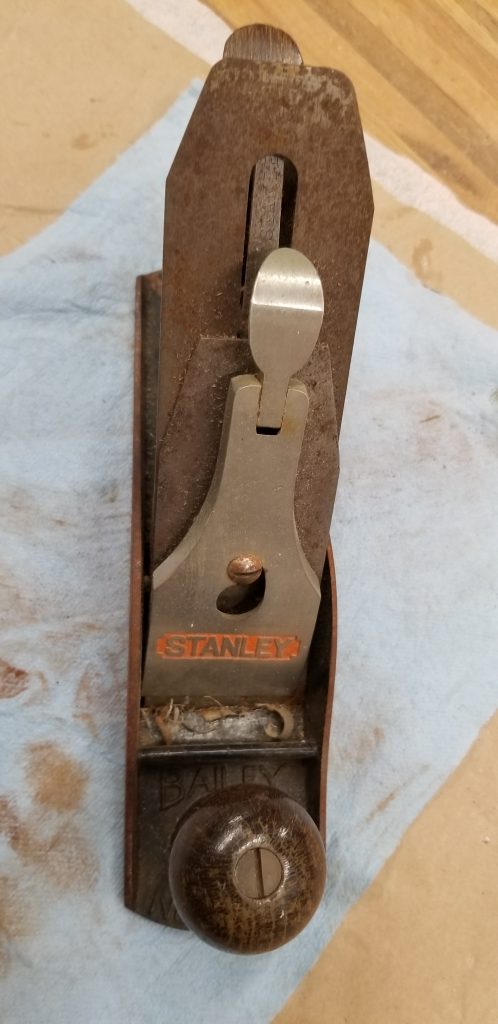
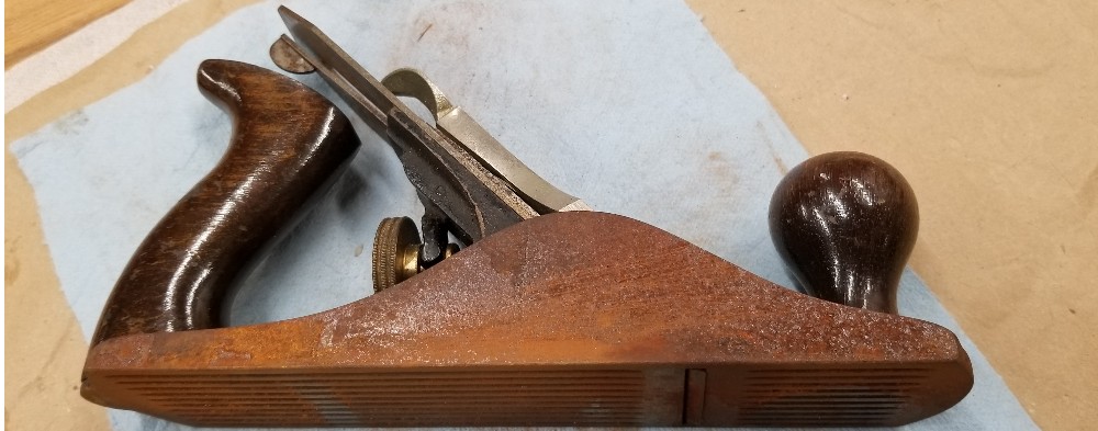
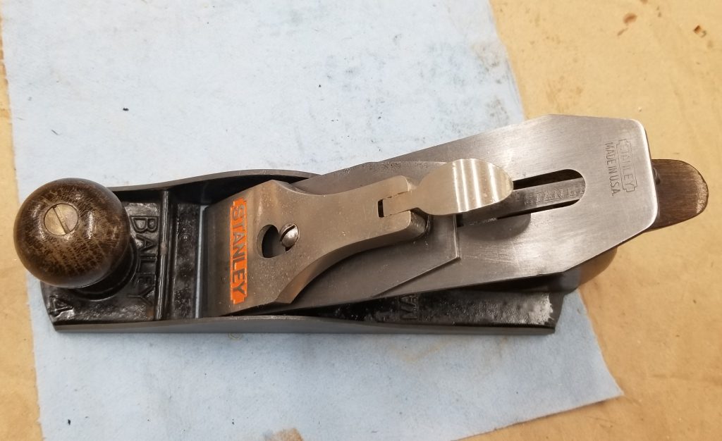
Last time I visited my brother, he handed me an old plane that he wasn’t using and that was gathering rust. Disused, but a good plane.
Here’s one view of the plane. It’s a Stanley plane, made in the USA. The markings on it say “Bailey No 4”. According to an online source, it is a Stanley Bailey Type 20 Handplane manufactured in the ’60s.
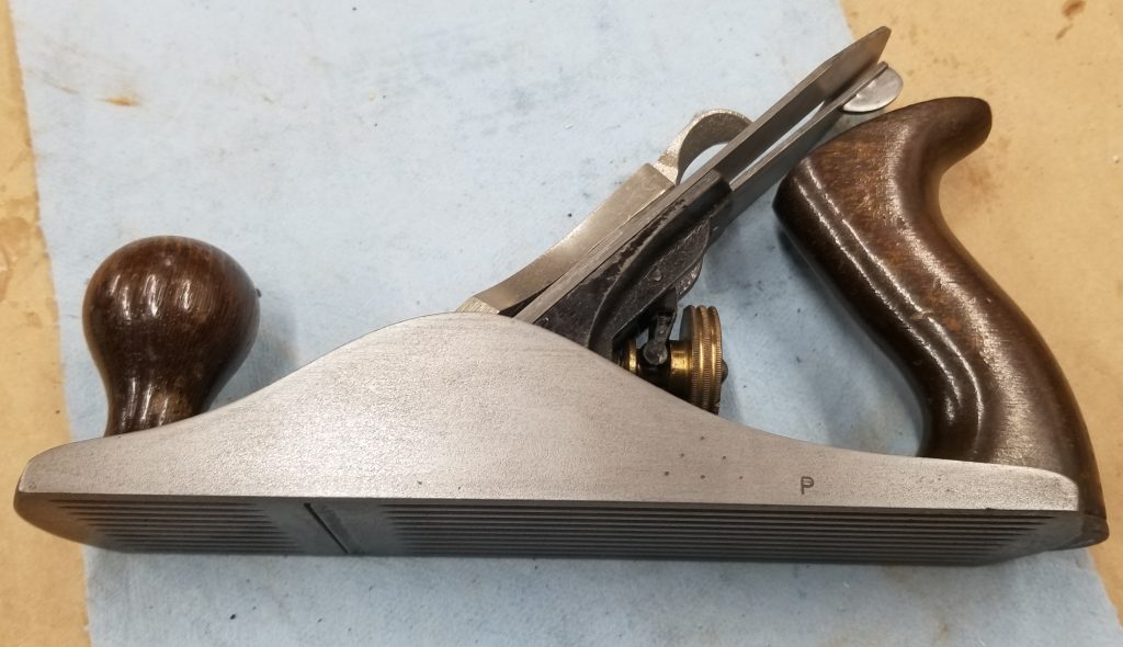
Viewed from the side, the rust is very obvious.
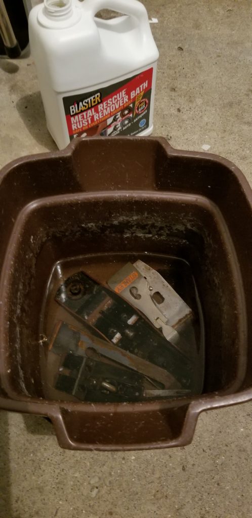
Step 1: Complete disassembly. The rust is everywhere and there is some other schmutz on some of the surfaces.
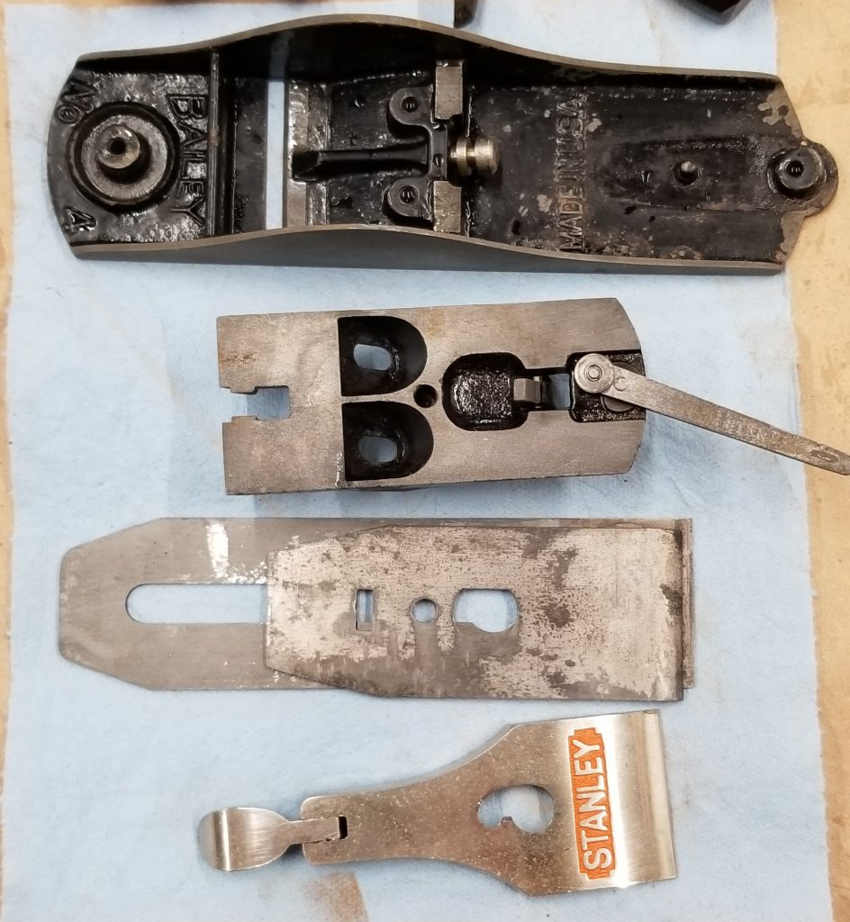
Step 2: The next move is to drop all the metal parts into a bath of rust remover. I let them sit for about 24 hours.
Rinsed and dried off, they look a lot better. The rust is almost all gone but there is still some surface stuff that wasn’t rust to start with.
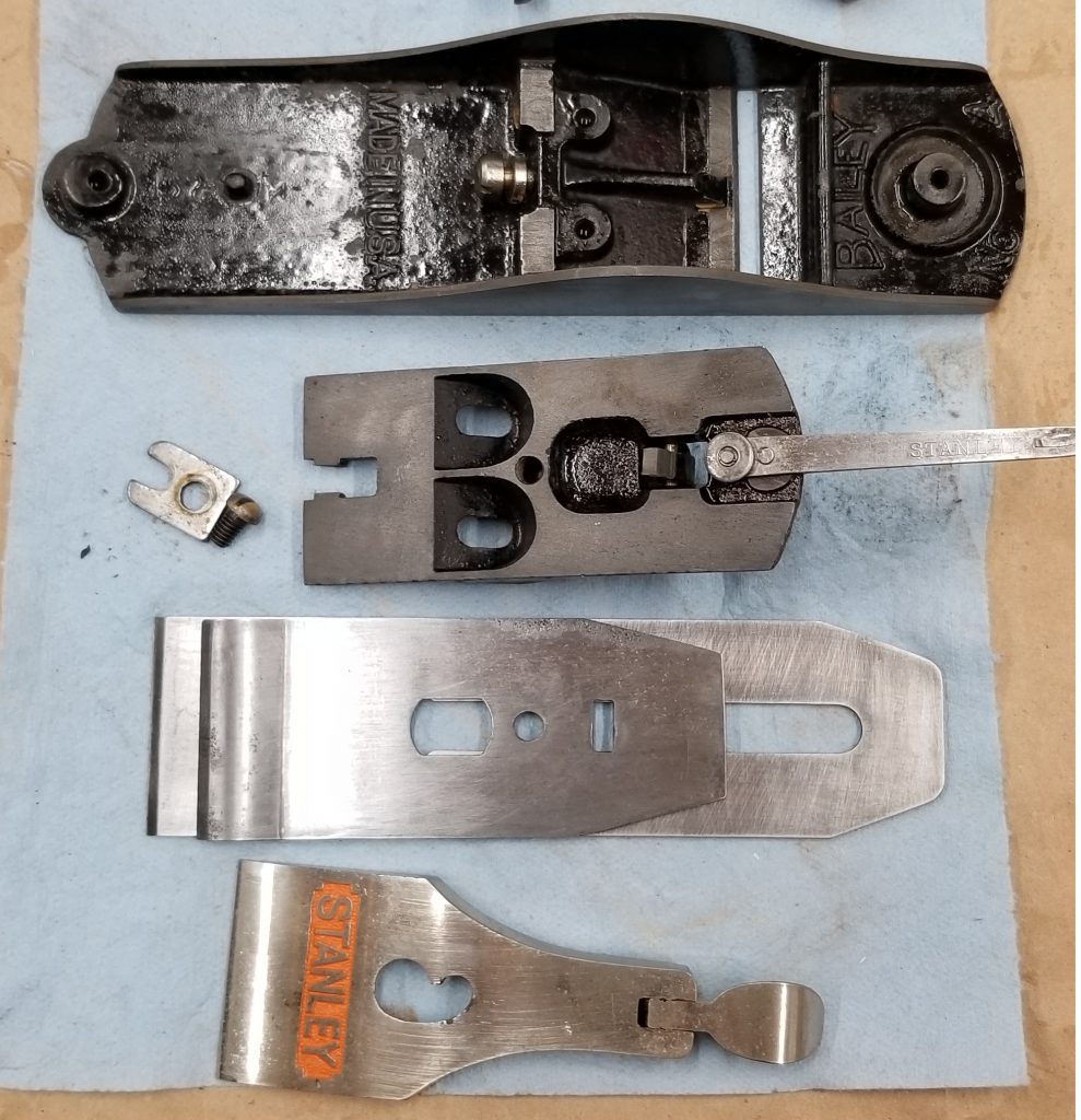
Step 3: Some work with a wire brush and sandpaper has cleaned up the surfaces. Add a very light coat of oil to inhibit future rust.
I may have left some scratch marks in the surface, but I can live with that. This thing isn’t going into a museum; it’s going into my shop.